Braking System for the Formula Buckeyes FSAE Car - 2021
- Morgan Malencia

- Mar 2, 2021
- 4 min read
Updated: Mar 8, 2021
Over the past three seasons, I have been in charge of designing, simulating, fabricating, and testing the outboarding braking system for the Formula Buckeyes FSAE car.

As the brakes lead, I am in charge of everything from the balance bar to the rotors. I work closely with the ergonomics team to develop the brake pedal to ensure flawless integration of the two systems. While it is important the driver is comfortable while driving the vehicle, all the components must be structurally sound and withstand the forces of high performance racing.
Design

The design aspect of the braking system includes finding master cylinders, calipers, and brake pads to suit the team's needs based on the FSAE rule book regulations and vehicle dynamic needs. Additionally, the rotors, mounts, and brake pedal are designed and manufactured in house.
The team's general design process includes planning, understanding the requirements, design matrices, modeling, analysis and simulation, fabrication, testing, and evaluation of all components. This path is often not linear and involves many adjustments and fine tuning before it is all over.
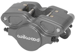
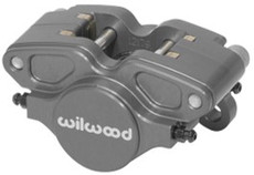
For the braking system, the first step is analyzing all of the necessary calculations to determine how much force will be required to lock all four wheels based on the deceleration, weight transfer, vehicle parameters such as center of gravity height, and the frictional force of the tire on the ground. Once an approximation is found, calipers that are able to provide that amount of force are chosen. The team has used Wilwood 2 piston calipers of various piston sizes over the years. Once the caliper piston size is decided, master cylinder bore sizes that fit the force generation requirement without an extreme amount of driver input are chosen. The team uses Tilton master cylinders as they are small enough to package in the vehicle and have many bore size options to chose from. The MC bore sizes are determined in conjunction with the balance bar. As required by the FSAE rules, there must be two master cylinders so a balance bar is used to connect them to the brake pedal. While it is possible to have two of the same sized MCs and very biased braking, it is more practical to have a larger bore size for the rear brakes so the balance bar can be positioned at approximately the center.
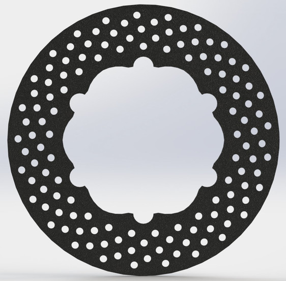
Once all the components to be purchased are selected and the forces that will be going into the system are known, the brake rotors are designed. Drilled rotors are used based on their superior ability to dissipate dust and gas compared to blank profiles. The rotors are attached to the spindles via brake buttons that allow some axial motion to decrease vibration and prevent cracking.
Modeling and Simulation
Solidworks and Ansys are used for modeling and simulation; respectively. While each sub-team lead designs their parts individually, it all comes together into a full vehicle assembly, shown below.

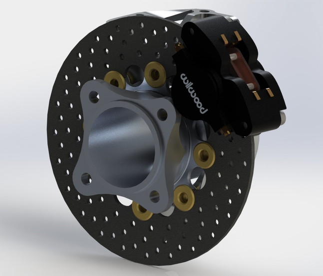
In the slideshow below, the front rotors, rear rotors, and rotor/calipers/upright/spindle assembly renders are shown.


In the slideshow below, the front rotor Ansys simulations are shown. The first image is the rotor under the maximum loading condition it will see which is the force to lock the brakes. The second image shows the temperature of the rotor after one, 2 second braking event. The last image shows the maximum temperature and the maximum force conditions the rotors are expected to see.
Model parameters:
- Quadratic mesh at 0.0008 m element size.
- Cylindrical supports at the brake buttons with axial motion free.
- Approximately 3000 N normal force and 1500 N frictional force at the brake pad face.
- Temperature to 450 C.


Manufacturing
The main manufacturing done for the brakes subsystem are the rotors, sensor mounts, and assisting the ergonomics team with the brake pedal box and balance bar. The mounts are 3D printed and the pedal box is generally done on the CNC mill.
Rotor Machining Process
The rotors are cut to approximately 0.03" thicker than the desired thickness on the lathe inhouse. Below are images of the manufacturing process including:
The aluminum jig that was created to ease manufacturing and ensure flatness.
A rotor blank with a hole drilled through the center attached to the jig.
The setup to actually cut the material.
One side completed.
The final rotor at around 0.18" thick.


After this process is complete, the blanks are sent to get waterjet cut out to the correct profiles. The last step is to get them Blanchard grinded to exact thickness and near perfect flatness.
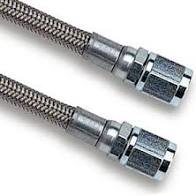
Below are some images of the main components used in the system that are purchased.


The next step in the manufacturing processes is assembly onto the vehicle. This is done after the chassis and suspension components have been completed and involves mounting the rotors, calipers, and master cylinders, as well as cutting and bending all brake lines. The brakes are bled and the rotors and pads are bedded once the vehicle is fully assembled.
Testing
The final phase is the testing phase. This involves the full vehicle being completed and in a functioning state. The team is fortunate enough to have access to a proving grounds to do all of our testing on. This provides a near perfect and flat surface to run rolling frictional tests, braking force and deceleration tests, and laps of autocross and endurance to test rotor temperatures. The electronics team is responsible for setting up the data acquisition system and collecting data, but this data is analyzed by the sub-teams depending on the purpose of the test.
The ultimate test is the FSAE competitions in Michigan, California, Canada, and Europe. The team typically goes to the Michigan and Canada competitions with 120 and 40 teams each, respectively. This allows us to prove the functionality and performance of our vehicle and learn a lot about how other teams tackle issues and solve problems. The Ohio State University got 31st place in Michigan and 9th place in Canada in 2019.
*Data withheld to maintain academic integrity.*


Comments